How To Install A Disc Coupling
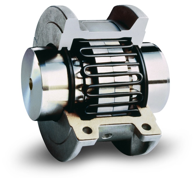
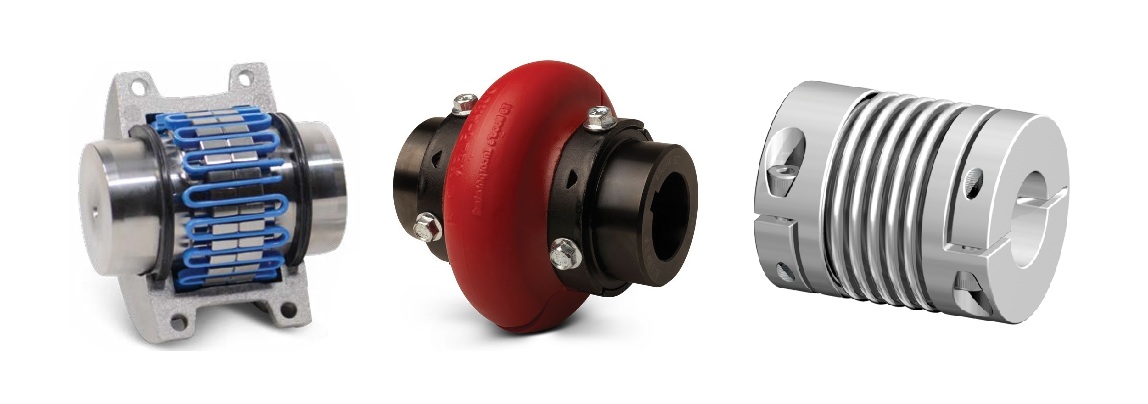
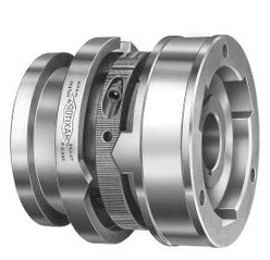
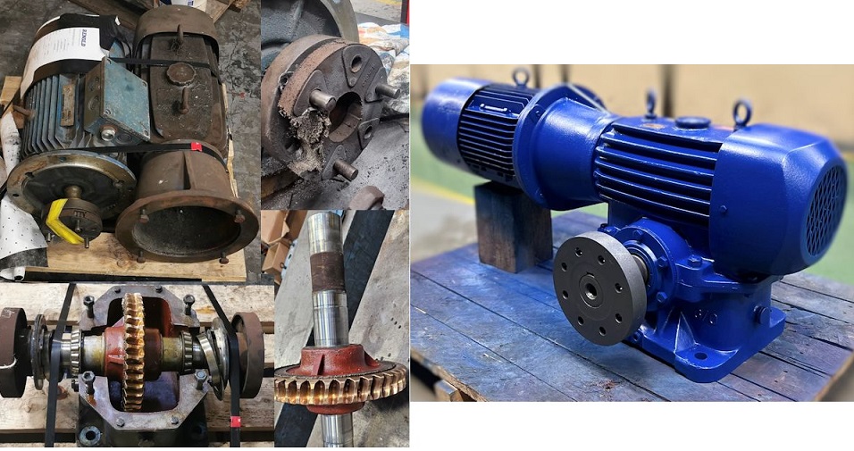
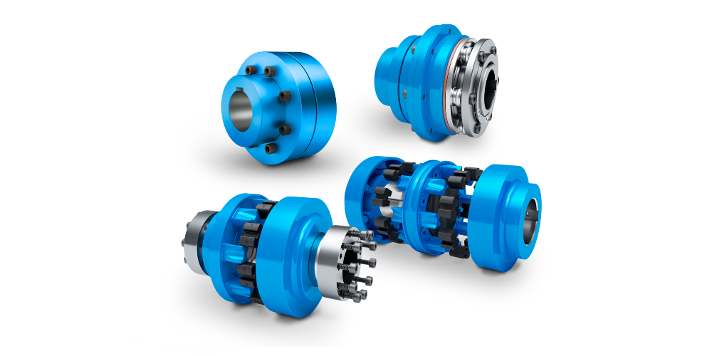
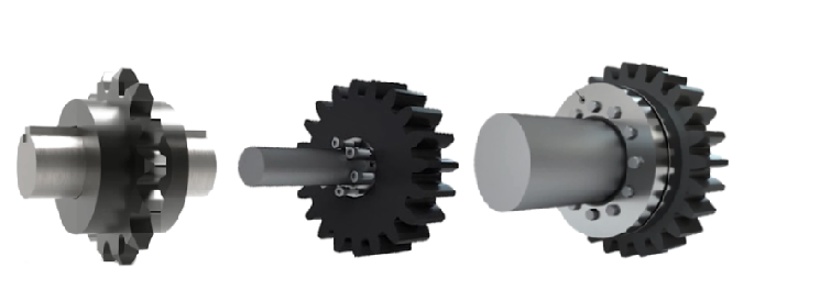
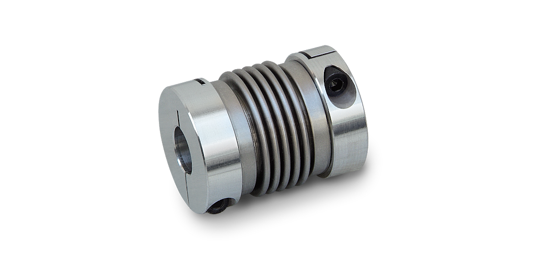
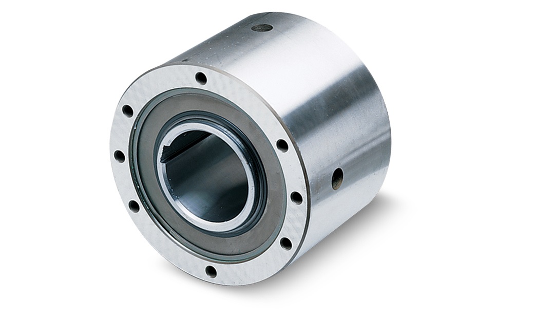
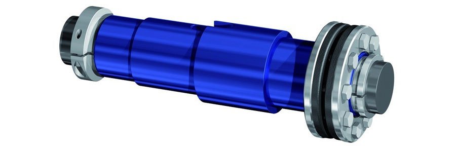
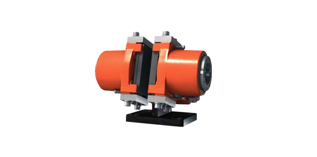
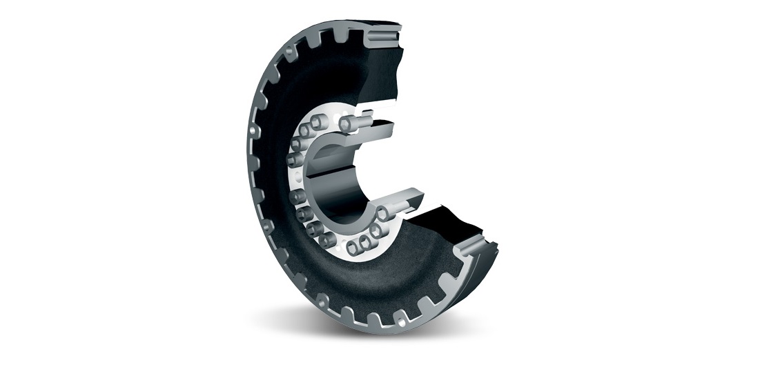
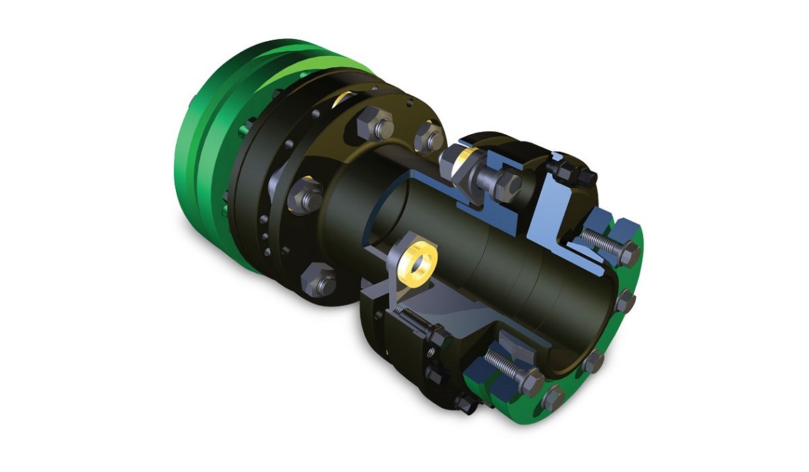
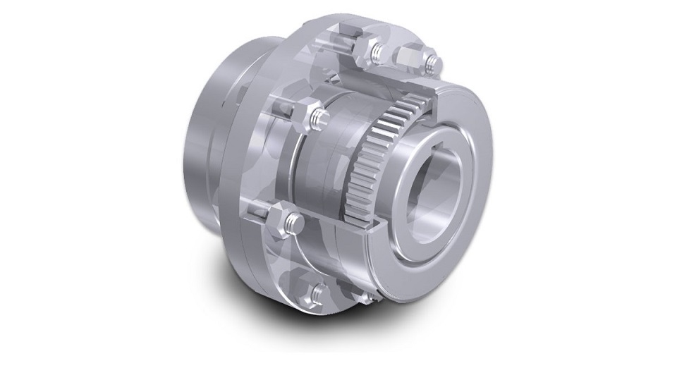
Disc couplings, known for their simplicity and efficiency, consist of two hubs, a center member, two-disc packs, and fastening hardware. Follow these expert tips to ensure a successful disc coupling installation that promises years of dependable service.
1) Safety and Inspection
Before starting the installation process, prioritize safety by wearing the appropriate personal protective equipment (PPE) and following lock-out tag-out procedures for stationary equipment. Thoroughly inspect the driving and driven shafts, along with the hub bores, ensuring they are free from dirt and burrs. Clean, de-burr as needed, and measure bore and shaft diameters for a precise fit. If the bore is tapered, check for a proper contact pattern and ensure keys fit snugly on the shaft with chamfered corners.

2) Mount the Hubs
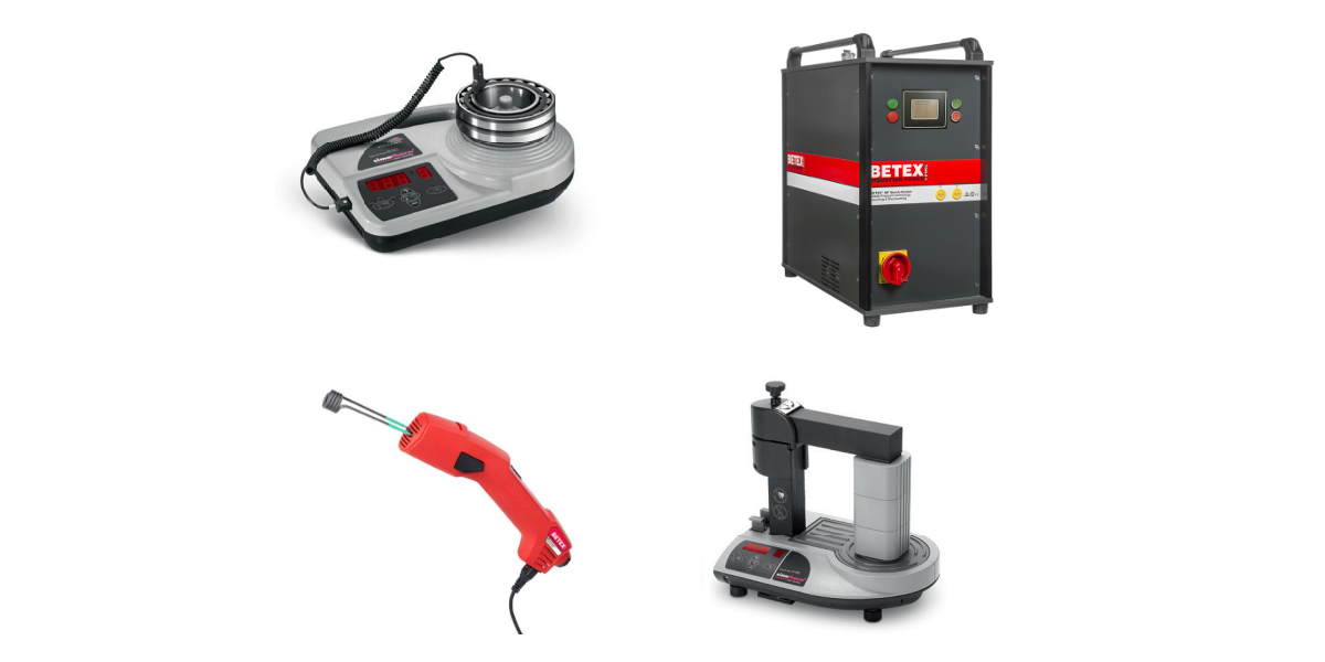
Begin by installing the key(s) in the shaft. Heat the hub in an oven to expand the bore adequately for interference fit bores. Ensure set screws in the hub do not protrude into the keyway for clearance fit bores. Slide the hub onto the shaft, utilizing axial stops for accuracy. For interference fits, tighten set screws to the torque specified in the manufacturer’s installation guide.

3) Check Alignment
Angular Misalignment
Securely fix a dial indicator onto one hub, positioning it on the face of the opposing hub. Rotate both shafts together for a complete revolution, taking note of the minimum and maximum dial indicator readings. The disparity between these values mustn't surpass the TIR value outlined in the manufacturer’s installation guide.

Parallel Misalignment
Mount a dial indicator firmly onto one hub, aligning it with the flange outside diameter of the other hub. Rotate both shafts simultaneously through a full revolution, observing and recording the minimum and maximum dial indicator readings. The difference between these values should stay within the TIR value specified in the manufacturer’s installation guide.

Axial Misalignment
The axial spacing of the hubs should be positioned so the disc packs are flat with no visual waviness. The distance between the hub faces, sandwiching the disc packs, must adhere to the prescribed limits for the “N” dimension, as detailed in the manufacturer’s installation guide.

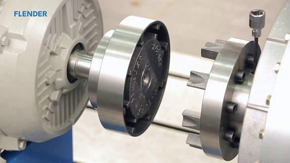
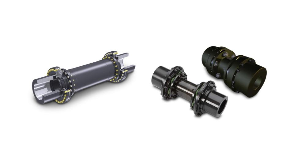
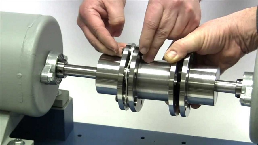
4) Attach the Center Member to the Hubs
Depending on the coupling design, choose the appropriate center member configuration. For adapter-mounted center members, compress the assembly to fit between piloted hubs. Reverse-install center member mounting capscrews to compress disc packs evenly. After placement, loosen compression capscrews to allow the center member assembly to expand.

5) Insert and Tighten the Cap Screws
Remove compression capscrews and insert them through the hubs, threading into the center member adapter holes. Tighten to the torque specified in the manufacturer’s installation manual.

6) Check the Final Shaft Alignment
Reassess the final alignment by measuring each disc pack's "N" dimension at various positions. Ensure alignment falls within the range outlined in the manufacturer’s installation manual.

Following these steps and ensuring the proper installation of the disc couplings allows the machinery's smooth operations and provides years of reliable service.
HVH Industrial Solutions is an authorized distributor of Rexnord, Lovejoy, Flender, Ringfeder, and many other disc coupling manufacturers. We work closely with their engineering team to provide superior customer service and engineering support.
If you have any questions, write to us via live chat or call or send us a quote request. The HVH team is always ready to help you.
Requesting ...
File size should not exceed 20 MB.
Are you sure you want to delete file?