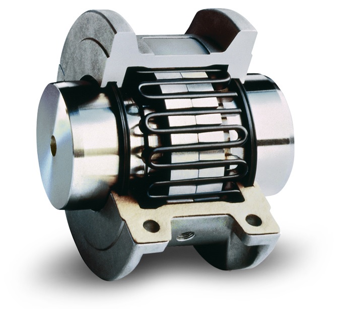
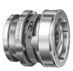
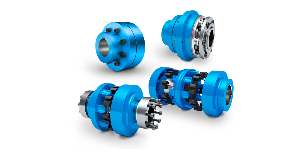
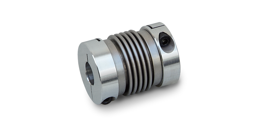
Step-by-Step Guide for FLENDER N-EUPEX Coupling Installation
Follow our step-by-step guide for FLENDER N-EUPEX Coupling installation. Ensuring a secure and efficient assembly begins with adhering to essential safety measures and equipping yourself with the right protective gear. Follow these straightforward instructions to optimize the longevity and performance of your N-EUPEX coupling.
Note: Before starting the assembly process, ensure that all safety precautions are taken, and appropriate personal protective equipment is worn.
1. Shaft and Component Inspection
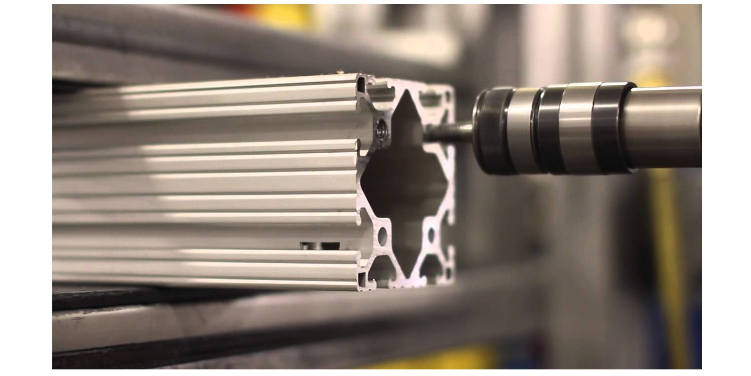
Inspect shafts for cleanliness and debris.
Check for damages on shafts and key; ensure smooth surfaces.
Examine coupling bores, keyways, and edges for cleanliness and damage.
2. Surface Preparation
Coat shaft surfaces with molybdenum sulfide assembly paste for fretting corrosion prevention and ease of disassembly.
Confirm all surfaces and edges are smooth and well-prepared for assembly.
3. Set Screw Handling
Finished board couplings are provided with the appropriate size set screws already installed.
Back the set screw out far enough so that it does not extend into the couplings keyway and interfere with the key or shaft during the assembly.
Alternatively, set screws can be completely removed and stored in a safe, easily accessible place for future use.
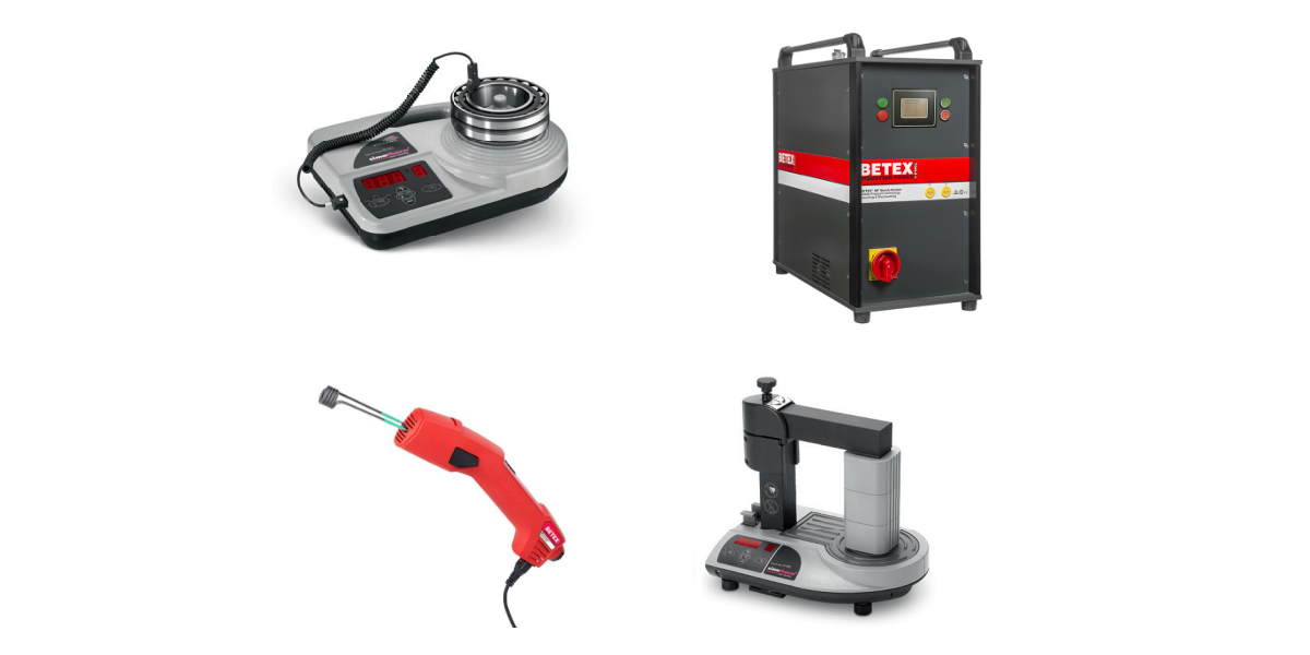
4. Hub Heating:
Determine if a transitional or interference fit is recommended for your application.
Use a heater or oven designed for this purpose. Heating the hubs will expand the bore size, which will facilitate the assembly
Check operating instructions for the recommended temperature for hub expansion.
With appropriate safety equipment, carefully position the heated hub on the shaft.
Slide into place, ensuring the end of the shaft is flush with the hub surface.
5. Flexible Element Precautions
If the hub temperature exceeds 100°C or 212°F, remove standard flexible elements before heating.
Note that different flexible elements have varying temperature limits.
Repeat the hub heating process for the second hub, adjusting the temperature based on the fit required.
Position the heated hub on the shaft, ensuring proper alignment and flush contact.
If set screws were removed, reinsert and hand-tighten.
6. Set Screw Torque Application:
Utilize an appropriate torque wrench to tighten the set screws to the recommended torque.
Refer to the operating manual for the specified torque settings.
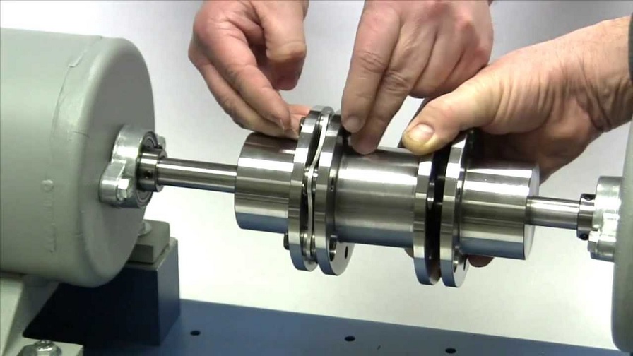
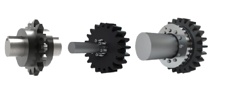
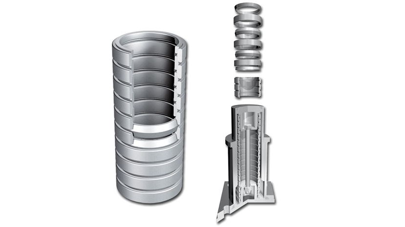
7. Flexible Element Insertion:
After the coupling has cooled down enough, insert new flexible elements to ensure even load distribution. Always use new flexible elements when putting a coupling into service, never combine old with new flexible elements. This is necessary to ensure an even load distribution and therefore a long lifetime
Note that the elements are molded to match the curve of the coupling, therefore be sure to insert the elements the right way round.
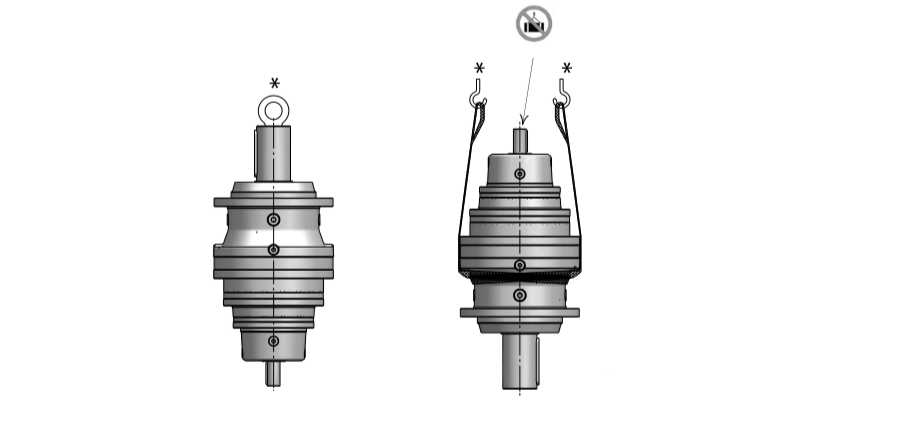
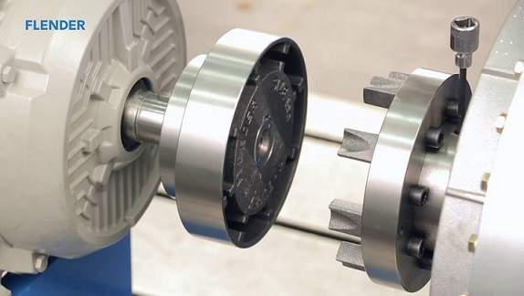
8. Machine Alignment:
Move one connected machine towards the other.
Ensure that the cams align to fit between the flexible elements.
Align the hubs by placing a straight edge across both hubs.
Make corrections as needed to achieve full contact across both hubs.
9. Angular and Radial Alignment:
Repeat the alignment process at multiple positions around the coupling diameter.
Ensure proper angular and radial alignment for stability.
10. Axial Alignment Verification:
Use a feeler gauge to verify axial alignment.
Refer to the operating instructions for the correct clearance specifications.
Check dimensions at multiple positions around the coupling diameter.
11. Drive Alignment:
Align the drive to reach the average dimension.
Tighten the screws on the connected units to their specified torque.
12. Completion:
Your N-EUPEX coupling is now properly aligned and ready for operation, providing efficient performance and longevity.
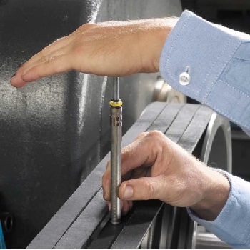
Note: The application of the wear indicator will give you an invaluable maintenance advantage to check for flexible element wear while the coupling is still in operation. It is no longer required to stop the operation of your equipment, apply the wear sticker according to the instructions, then while the drive is still in operation you'll be able to use a strobe light to actually see how much the elements have worn and know when to replace them.
Also, check our article, The Power and Precision of Flender's N-EUPEX Couplings, to learn more about N-EUPEX Couplings.
HVH Industrial Solutions is an authorized distributor of Flender. We work closely with their engineering team to provide superior customer service and engineering support.
If you have any questions, write to us via live chat or call or send us a quote request. The HVH team is always ready to help you.
Requesting ...
File size should not exceed 20 MB.